Unifi Network VLAN setup with IoT and access to Pi-hole
Introduction
Section titled “ Introduction”This guide covers the setup of VLANs and WiFi networks using the Unifi Network Application. It also provides instructions for configuring the firewall to enable devices on any VLAN to utilize the Pi-hole.
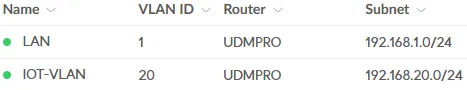
I have created the following networks:
- LAN (this is the default network and renamed to LAN) - very trusted - this contains all network equipment
- SERVER-VLAN - very trusted - this contains servers and a NAS
- CLIENT-VLAN - trusted - this contains clients like desktops, laptops, tablets and phones
- IOT-VLAN - not trusted - this contains smart(home) devices and media players
- GUEST-VLAN - not trusted - this contains not trusted clients including devices from work
Network setup
Section titled “Network setup”Determine the VLAN ID each VLAN should have
Section titled “Determine the VLAN ID each VLAN should have”For the IOT-VLAN I use VLAN ID 20 for example. This number will match the Gateway IP/Subnet: 192.168.20.0/24.
Create the IOT-VLAN
Section titled “Create the IOT-VLAN”-
Go to
SettingsandNetworks -
Create a
New Virtual NetworkAll settings remain at their default values except for the modifications detailed below.Instructions:
- Required Network Name:
IOT-VLAN - Required Gateway IP/Subnet: Uncheck
Auto-Scale Networkand change the Host Address to192.168.20.1with Netmask24
Advanced:
First selectManual.- Required VLAN ID:
20 - Optional Multicast DNS: please read [[Unifi Network - Setup Chromecast between VLANs]] for more information
DHCP:
- Required DHCP Range Start:
192.168.20.150 - Required DHCP Range Stop:
192.168.20.254
Now expand
Show optionsafterDHCP Service Management.- Optional DNS Server: In my case I unchecked
Autoand added the IP address of my Pi-hole - Optional Domain Name:
home.arpa
- Required Network Name:
-
Click
Add
Repeat the above steps for any other VLAN.
Port management
Section titled “Port management”Now that the networks/VLANs have been created, we can adjust the switch port settings. With this we ensure that wired devices use the correct VLAN and, for example, will receive the correct IP address. For wireless devices, we will create the corresponding WiFi networks in the WiFi Setup part.
Change the port settings
Section titled “Change the port settings”-
Go to
Ports, or alternatively go toUnifi Devices, click on a switch or the router and click thePort Managerbutton -
Go to the tab
Ports, if this is not already selected -
Now you can select a port and change the settings
For example:
- Optional Name:
P1Reader- this is the name of the IoT device - Required Native VLAN / Network:
IOT-VLAN (20) - Required Tagged VLAN Management:
Block All - Optional PoE: you can turn PoE off if the device does not need Power over Ethernet
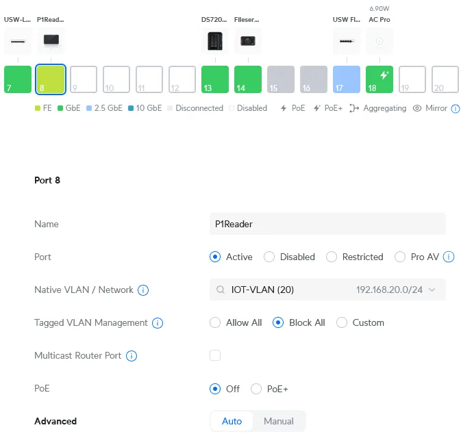
- Optional Name:
-
And finally click
Apply Changes.
Repeat this for all ports for which it is necessary to change the port settings.
Check the results
Section titled “Check the results”To check if the port settings are working properly, do the following:
-
Go to
Client Devices -
And there is the P1Reader within the IOT-VLAN network and a corresponding IP address:

-
Give the client device a fixed IP address if needed
- Optional Click on the device and go to
Settingsand give it a fixed IP address, which I did for the above P1Reader example
- Optional Click on the device and go to
WiFi setup
Section titled “WiFi setup”To ensure that wireless devices connect to the correct network, I have created three WiFi networks:
- WiFi-Client
- WiFi-IoT
- WiFi-Guest
All settings remain at their default values except for the modifications detailed below.
-
Go to
SettingsandWiFi -
Click
Create New:Instructions:
- Required Name: for example
WiFi-IoT - Required Password: Your password
- Required Network: for example
IOT-VLAN- or linkWiFi-ClienttoCLIENT-VLANandWiFi-GuesttoGUEST-VLAN
Advanced:
First selectManual.- Required Client Device Isolation: I have enabled this only for the
WiFi-Guestnetwork - Optional WiFi Speed Limit:
Default- for theWiFi-Guestnetwork I have created a guest profile that limits the bandwidth slightly - Optional Multicast Enhancement and Multicast and Broadcast Control: please read this note for more information
- Optional MAC Address Filter: I have enabled the filter for
WiFi-ClientandWiFi-IoT - Optional Security Protocol: use
WPA2for backwards compatibility, so I usedWPA2forWiFi-IoTenWPA2/WPA3forWiFi-GuestandWiFi-Client. At some point I will completely switch toWPA3 - Optional Group Rekey Interval:
Enable 3600 seconds- for increased security
- Required Name: for example
-
And finally click
Add WiFi Network.
Repeat the above steps for any other WiFi network.
Firewall setup
Section titled “Firewall setup”To make the VLANs work properly the first rule I created is to allow established/related sessions from client devices. Then I made sure traffic between the networks is no longer possible. Blocking inter-VLAN routing is also described by Ubiquiti here.
RFC1918 IP group
Section titled “RFC1918 IP group”First create the IP Group needed for blocking inter-VLAN routing:
- Go to
SettingsandProfiles - Go to tab
IP Groups - Create a new profile
Instructions:
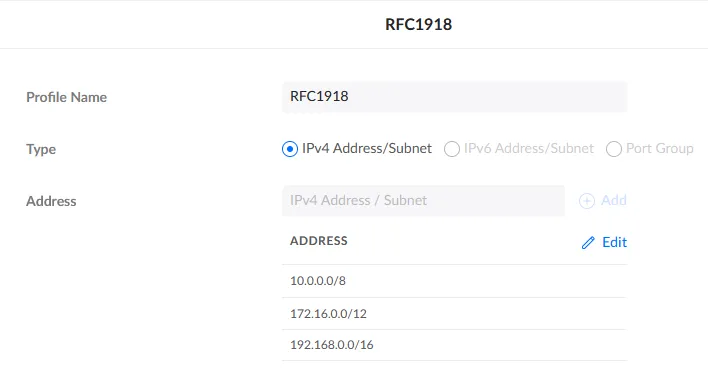
- Required Profile Name:
RFC1918 - Required Type:
IPv4 Address/Subnet - Required Address: add
10.0.0.0/8,172.16.0.0/12, and192.168.0.0/16
- Required Profile Name:
- Click the
Addbutton (all the way at the bottom left)
You can now use this IP group when creating the firewall rule.
Select LAN In rules
Section titled “Select LAN In rules”- Go to
SettingsandSecurity - Go to tab
Traffic & Firewall Rules - Go to
LANrules and selectLAN In
All settings remain at their default values except for the modifications detailed below.
Rule allow established/related sessions
Section titled “Rule allow established/related sessions”-
Click
Create Entryand make sureRule Typeis set toAdvancedInstructions:
- Required Type:
LAN In - Required Name:
allow established/related sessions, for example - Required Action:
Accept - Required Protocol:
AllandBefore Predefinedis selected
Advanced:
First selectManual.- Required Match State: Only
EstablishedandRelatedare selected
- Required Type:
-
Leave the other fields at their default value and click the
Add Rulebutton (all the way at the bottom left)
Rule drop traffic between vlans
Section titled “Rule drop traffic between vlans”- Click
Create Entryand make sureRule Typeis set toAdvancedInstructions:
- Required Type:
LAN In - Required Name:
drop traffic between vlans, for example - Required Action:
Drop - Required Protocol:
AllandBefore Predefinedis selected
Source:
- Required Source Type:
Port/IP Group - Required Address Group:
RFC1918
Destination:
- Required Destination Type:
Port/IP Group - Required Address Group:
RFC1918
- Required Type:
- Leave the other fields at their default value and click the
Add Rulebutton (all the way at the bottom left)
Now all VLANs/networks are seperated from each other.
The rules below will make it possible that:
- All VLANs has access to Pi-hole DNS
- LAN has access to all other networks
- CLIENT-VLAN has access to LAN (or make sure that you allow individual devices from the CLIENT-VLAN to manage LAN)
- CLIENT-VLAN has access to SERVER-VLAN
- CLIENT-VLAN has access to IOT-VLAN
- Some IOT-VLAN devices has access to SERVER-VLAN
This seems to me personally a good basis to start with. The next step could be to set up access between the VLANs in more detail.
Rule allow dns from vlans
Section titled “Rule allow dns from vlans”- Click
Create Entryand make sureRule Typeis set toAdvancedInstructions:
- Required Type:
LAN In - Required Name:
allow dns from vlans, for example - Required Action:
Accept - Required Protocol:
AllandBefore Predefinedis selected
Source:
- Required Source Type:
Port/IP Group - Required Address Group:
RFC1918
Destination:
- Required Destination Type:
Port/IP Group - Required Address Group: Create a new
IP Groupand add the IP address(es) of your Pi-hole(s) - Required Port Group: Create a new
Port Groupand add port53
- Required Type:
- Leave the other fields at their default value and click the
Add Rulebutton (all the way at the bottom left)
Rule allow lan to all vlans
Section titled “Rule allow lan to all vlans”- Click
Create Entryand make sureRule Typeis set toAdvancedInstructions:
- Required Type:
LAN In - Required Name:
allow lan to all vlans, for example - Required Action:
Accept - Required Protocol:
AllandBefore Predefinedis selected
Source:
- Required Source Type:
Network - Required Network:
LAN - Required Network Type:
Ipv4 Subnet
Destination:
- Required Destination Type:
Port/IP Group - Required Address Group:
RFC1918
- Required Type:
- Leave the other fields at their default value and click the
Add Rulebutton (all the way at the bottom left)
Rule allow clients to lan
Section titled “Rule allow clients to lan”- Click
Create Entryand make sureRule Typeis set toAdvancedInstructions:
- Required Type:
LAN In - Required Name:
allow clients to lan, for example - Required Action:
Accept - Required Protocol:
AllandBefore Predefinedis selected
Source:
- Required Source Type:
Network - Required Network:
CLIENT-VLAN - Required Network Type:
Ipv4 Subnet
Destination:
- Required Source Type:
Network - Required Network:
LAN - Required Network Type:
Ipv4 Subnet
- Required Type:
- Leave the other fields at their default value and click the
Add Rulebutton (all the way at the bottom left)
Rule allow clients to servers
Section titled “Rule allow clients to servers”- Click
Create Entryand make sureRule Typeis set toAdvancedInstructions:
- Required Type:
LAN In - Required Name:
allow clients to servers, for example - Required Action:
Accept - Required Protocol:
AllandBefore Predefinedis selected
Source:
- Required Source Type:
Network - Required Network:
CLIENT-VLAN - Required Network Type:
Ipv4 Subnet
Destination:
- Required Source Type:
Network - Required Network:
SERVER-VLAN - Required Network Type:
Ipv4 Subnet
- Required Type:
- Leave the other fields at their default value and click the
Add Rulebutton (all the way at the bottom left)
Rule allow clients to iot
Section titled “Rule allow clients to iot”- Click
Create Entryand make sureRule Typeis set toAdvancedInstructions:
- Required Type:
LAN In - Required Name:
allow clients to iot, for example - Required Action:
Accept - Required Protocol:
AllandBefore Predefinedis selected
Source:
- Required Source Type:
Network - Required Network:
CLIENT-VLAN - Required Network Type:
Ipv4 Subnet
Destination:
- Required Source Type:
Network - Required Network:
IOT-VLAN - Required Network Type:
Ipv4 Subnet
- Required Type:
- Leave the other fields at their default value and click the
Add Rulebutton (all the way at the bottom left)
Rule allow some iot to servers
Section titled “Rule allow some iot to servers”- Click
Create Entryand make sureRule Typeis set toAdvancedInstructions:
- Required Type:
LAN In - Required Name:
allow some iot to servers, for example - Required Action:
Accept - Required Protocol:
AllandBefore Predefinedis selected
Source:
- Required Source Type:
Port/IP Group - Required Address Group: Create a new
IP Groupand add the IP address(es) of the IoT device(s)
Destination:
- Required Destination Type:
Port/IP Group - Required Address Group: Create a new
IP Groupand add the IP address(es) of the server(s)
- Required Type:
- Leave the other fields at their default value and click the
Add Rulebutton (all the way at the bottom left)
Check the results
Section titled “Check the results”In this way I have created a few more rules. A number of things are accepted first and otherwise the traffic will be dropped between the VLANs. The firewall rules then look like this:
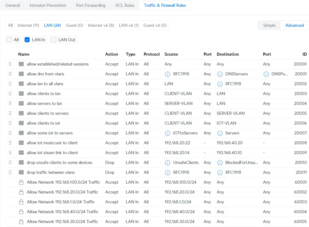
Test if it works, for example with your mobile phone by temporarily connecting to the IoT WiFi network.
No comments found for this note.
Join the discussion for this note on Github. Comments appear on this page instantly.